www.jb-electronics.de » Elektronik » Nixie-Röhren » Nixiefish
Nixiefish
Nixiefish - ein komischer Name - soll sich am englischen Wort jellyfish anlehnen, was Qualle bedeutet. Denn als Mensch mit Nixie-Röhren als Hobby bekomme ich interessante Dinge zu hören, wenn Freunde oder Bekannte mal eine Nixie sehen. Und so hörte ich letztens den Satz They look a little bit like jellyfish. Konkret ging es um einen Satz ZM1120, und diese Ähnlichkeit ist wirklich nicht von der Hand zu weisen, denkt mensch sich ein paar Tentakel dazu.
Das musste natürlich direkt in die Tat umgesetzt werden.
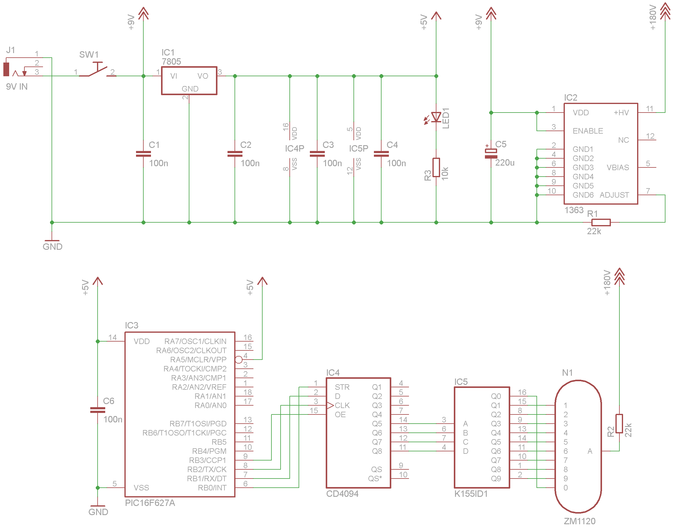
Schaltplan
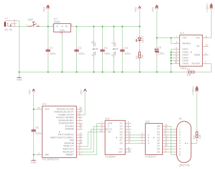
Hier ist eine höher auflösende Version des Schaltplans vorhanden.
Die Elektronik ist sehr simpel; die Eingansspannung ist 9V, ein Hochspannungsmodul wandelt diese in 180V für die ZM1120, und ein 7805-Wandler erzeugt 5V aus den 9V für den Controller und die Peripherie. Diese besteht aus einem CD4094 und einem K155ID1, der die Nixe ansteuert. Hinter der Nixie sitzt eine orange 3mm LED, die permanent leuchtet. Den CD4094 habe ich verbaut, da er mit seinem OE-Eingang eine gute Möglichkeit zum Dimmen des Signals bietet und uns so eine Hochspannungs-Treiberstufe erspart.
Software
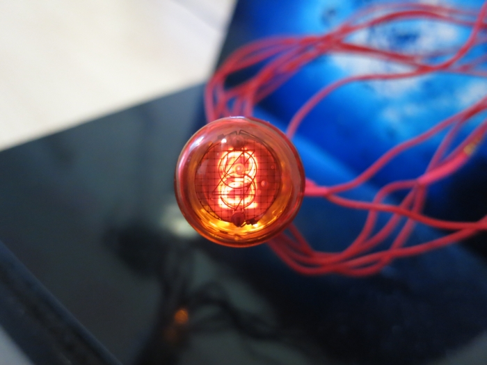
Die Ziffern der Nixie werden wie in einer Slotmaschine der Reihe nach von hinten nach vorne durchgeschaltet, weshalb im Programmcode das Array digit_stack die Reihenfolge der Ziffern in der ZM1120 angibt; die Ziffer 4 ist ganz vorne. Dieses Array muss bei Verwendung anderer Nixies angepasst werden.
Parallel dazu wird die Helligkeit des Displays permanent herauf und heruntergefahren um einen pulsierenden Eindruck zu erwecken. Zusammen mit der orangenen permanent leuchtenden LED sieht das sehr interessant aus.
Die Dimm- und Slotmaschinen-Geschwindigkeit lassen sich mit den Variablen pwm_speed und digit_speed im Quellcode anpassen. Für alle Interessierten gibt es hier den C-Quellcode und das fertig kompilierte HEX-File: NixieFish.zip (3KB)
Aufbau
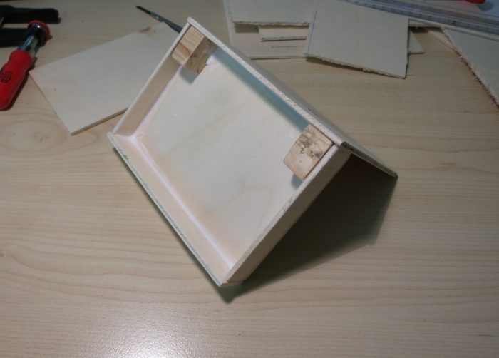
Aus Sperrholz baute ich ein kleines Gehäuse, in dem später die Elektronik Unterschlupf findet.
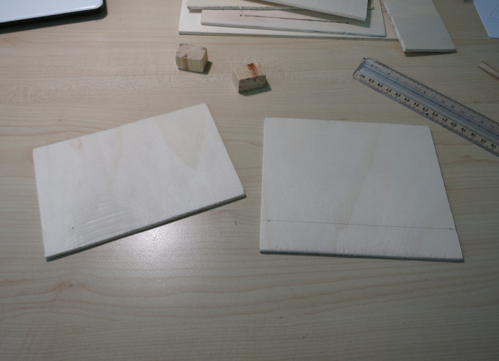
Auf die Innenseiten werden später zwei 10cm×15cm-Fotos mit einem Unterwasser-Motiv geklebt.
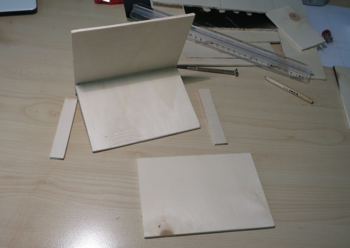
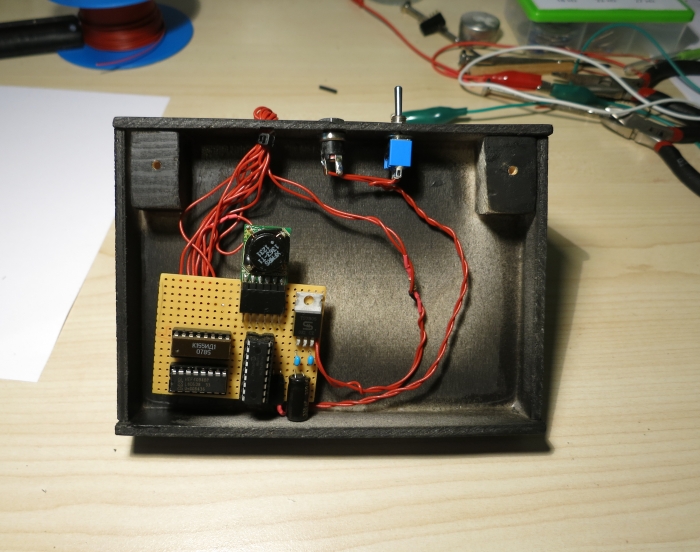
Es gibt ausreichend Platz für die Beschaltung:
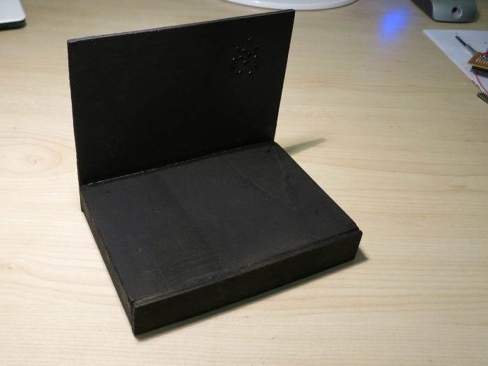
Danach wurde das Gehäuse schwarz angesprüht:
Hier ist die Platine mit Hochspannungsgenerator, PIC, und Nixie-Treibersrufe zu sehen:
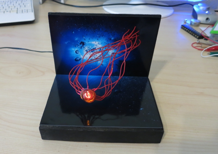
Der fertige Nixiefish
Dann wurde die Bodenplatte eingesetzt, die Fotos aufgeklebt, und die Nixie verdrahtet. Das Ergebnis:
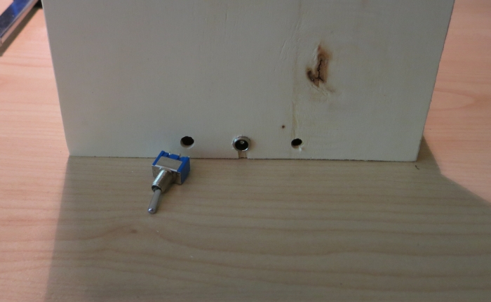
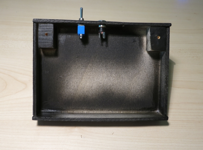
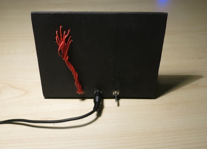
Auf der Rückseite sieht man die Verdrahtung der Nixie, die Stromversorgung, und den Ein-/Aus-Schalter.
Die Illusion einer Qualle ist nahezu perfekt gelungen:
